

Engine Rebuiling-Performance Engine Rebuilding-Automotive Machine Shop
Cylinder Head Surafcing CBN PCD Head Re -Surfacing
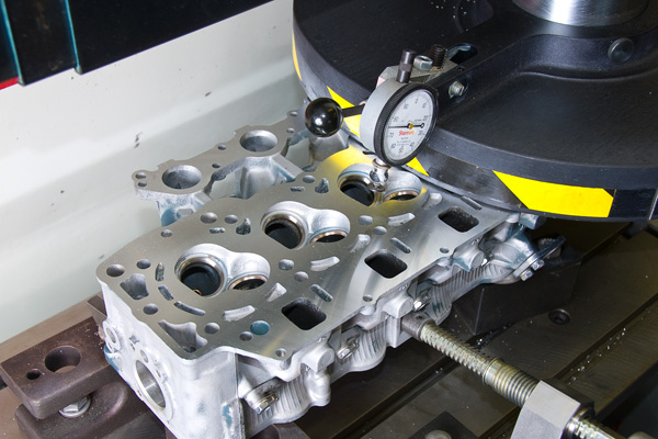
Cylinder Head Surfacing services include angle milling heads along with super finishing the gasket surface. Very low Ra surface finishes are required for MLS gasket surfaces. Our cylinder head re-surfacing process utilizes dual axis leveling table the most rigid set up available. Our Rottler CBN and PCD milling machine cylinder head surfacing machine utilizes precision ball screws for the table and infinitely variable work head RPM. The cycle is computer controlled while maintaining the exact constant surface feed required for super finishing the proper RA cylinder head surface finish.ylinder Head Surfacing services include angle milling heads along with super finishing the gasket surface. Very low Ra surface finishes are required for MLS gasket surfaces. Our cylinder head re-surfacing process utilizes dual axis leveling table the most rigid set up available. Our Rottler CBN and PCD milling machine cylinder head surfacing machine utilizes precision ball screws for the table and infinitely variable work head RPM. The cycle is computer controlled while maintaining the exact constant surface feed required for super finishing the proper RA cylinder head surface finish.
Rottler F69A CNC The Automatic Surfacing Cycle controls the precise feed rate and spindle RPM, amount of cut per pass and total depth. Parameters can be changed for a roughing and finishing cycle. Ideal when angle milling or removing large amounts of material.This is the ultimate tool for achieving very Low RA numbers ie. Super fine finishes.ottler F69A CNC The Automatic Surfacing Cycle controls the precise feed rate and spindle RPM, amount of cut per pass and total depth. Parameters can be changed for a roughing and finishing cycle. Ideal when angle milling or removing large amounts of material.This is the ultimate tool for achieving very Low RA numbers ie. Super fine finishes.

Engine Gaskets 101: The Sealing Science, Larry Charley, Counterman, October 2001
Ever wondered why engines need so many different gaskets? It's because engines have a lot of different sealing needs - thus translating into different sales situations that every counter person should know.
SURFACE MATING: CUT GASKET
When two surfaces are mated together, it's very difficult to get a leak-free seal unless something is used to fill in the gap. So various types of gaskets are used to essentially fill the gap between the parts.
The simplest and most basic type of gaskets are "cut" gaskets (also called "flat" gaskets). These are made by die-cutting sheets of fiber-reinforced paper-like material or ground cork/rubber to create the desired shape. Cut gaskets are typically used to seal timing chain covers, valve covers, oil pans, intake manifolds, carburetors, throttle bodies, water pumps, thermostat housings, transmission pans and differential covers.
Cut gaskets are usually the least expensive type because they are relatively easy to manufacture. They also allow a vehicle manufacturer to use less-expensive stamped steel valve covers, timing covers and oil pans on engines instead of more costly decals aluminum covers.
But cork/rubber cut gaskets don't last forever. Over time, exposure to heat causes the gasket material to lose its elasticity and become hard and brittle. This decreases the gasket's ability to maintain a leak-free seal and increases the risk of gasket breakage and failure.
MOLDED RUBBER
On most newer engines, many cut gaskets have been replaced by more durable (and more expensive), "molded rubber" gaskets. These are made by injection molding synthetic rubber (nitrile, neoprene, silicone, etc.) to create a one-piece gasket. Molded gaskets are most often used to seal die cast valve covers and oil pan covers.
Molded gaskets have several advantages over cut gaskets. One is that molded rubber gaskets retain their flexibility much better than cork/rubber cut gaskets. That makes them more durable and less likely to leak as the miles add up. This type of gasket can often be reused as long as it is in good condition.
But oil makes molded gaskets swell. This may prevent the gasket from fitting or sealing properly when an attempt is made to reinstall it. That's why a replacement is often recommended. (Warning: sealers or adhesives should never be used with molded rubber gaskets).
Another advantage of molded gaskets is easier installation when they're new. A one-piece molded rubber gasket for an application like the oil pan on a small block Chevy V8 eliminates the seams and joints that are required with a traditional multi-piece cut gasket set. This eliminates potential leak paths and makes installation easier, too.
Some molded gaskets also incorporate a steel "carrier" to provide added stiffness and reinforcement. This type of gasket is much easier to handle and install than a floppy rubber gasket that lacks any reinforcement. The gasket may also have built-in grommets to limit the amount of crush when the cover is tightened down.
Steel carriers and grommets are also used in some cork/rubber cut gaskets for the same purpose. What's more, several aftermarket gasket suppliers make less expensive cork/rubber cut gaskets that can be used to replace some molded rubber gaskets or "gasket less" applications that were originally sealed with RTV silicone sealer. Likewise, they also make special molded rubber gaskets to replace cork/rubber cut gaskets.
On some late-model engines, molded "composite" gaskets are used to seal the intake manifold to the cylinder head. With this type of gasket, a metal or plastic carrier is used to support O-rings or molded sealing beads around the port openings. Though these types of gaskets are very durable, they are also very expensive to manufacture and replace. In a few instances, a less expensive cut-style replacement gasket may be available - but usually not because of the design requirements of the engine. This same type of high-tech composite gasket construction is also used for some performance valve covers and thermostat housing gaskets.
HEAD GASKETS
One of the most demanding sealing applications on any engine is the head gasket. The head gasket's job is to seal the gap between the cylinder head and block. The head gasket has to withstand the effects of oil, coolant and gasoline as well as extremes of temperature and pressure.
Combustion temperatures can soar to over 4,000 degrees F under heavy load and average around 2,000 degrees F during normal driving. At the same time, combustion pressures change during the intake stroke to 400 to 600 pounds per square inch during the power stroke over 50 times a second at highway speeds!
To make matters worse, many head gaskets find themselves sandwiched between dissimilar metals that have different rates of thermal expansion. Most late-model engines have aluminum cylinder heads and cast iron blocks. Aluminum expands and contracts at over twice the rate of cast iron. This creates a lot of back-and-forth scrubbing on both surfaces of the head gasket that can literally tear a gasket apart over time if it is not designed to handle this kind of movement.
One way gasket manufacturers combat the scrubbing problem in bimetal engines is to apply nonstick coatings to their head gaskets. Most head gaskets today are a composite design with a soft non-asbestos facing material or graphite on a solid or perforated steel core. Teflon, molybdenum and similar coatings are used to prevent the gasket from sticking to either surface, allowing the head to expand and contract without ripping the gasket apart. This is the opposite approach to what was, and still is, used on many head gaskets for cast-iron engines. On these applications, raised silicone sealing beads are often used to improve cold sealing. The added thickness of the bead increases the clamping pressure in critical areas of the gasket, but also increases the grip against the head and block. This works fine if the head and block expand at the same rate, but it can create shearing forces in the gasket if the engine has an aluminum cylinder head.
On many late-model engines, the OEM head gaskets are graphite because graphite has natural lubricity to handle the differences in expansion between aluminum heads and cast iron blocks. Graphite is also a relatively soft material that has excellent cold sealing properties, and it can withstand high temperatures. It is an "anisotropic" material that can draw heat away from hot spots to reduce thermal stress and loading. But graphite is also expensive and more difficult to manufacture.
"Graphite is a good gasket material," said one aftermarket gasket engineer. "But it isn't necessarily the best material for every application. You have to choose whatever material works best in a given situation. For some engines that would be a non-asbestos material rather than graphite."
One of the drawbacks of graphite is that it must be protected to withstand exposure to oil over the long term. And although graphite has good seal ability, it can crush and extrude. That's why some aftermarket replacement gaskets for engines that came originally equipped with graphite are made of less expensive non-asbestos composite materials.
MULTI-LAYER STEEL (MLS)
The ultimate head gasket design today is multi-layer steel (MLS), which is used on Ford 4.6L V8s, other Ford engines, as well as Chrysler, Honda, Mazda and others makes. This design typically has three to seven layers of steel. The outer layers are usually stainless spring steel, embossed and coated with a thin layer of nitrile rubber or Viton to provide extra cold sealing. The inner layers provide added support and thickness.
MLS gaskets are extremely durable compared to other types of head gaskets because of their all-steel construction. They won't burn through, and they won't relax and take a compression set that can lead to leaks and sealing problems. MLS gaskets also reduce blow-by and improve compression by reducing bore distortion in the cylinders (less load is needed to seal this type of gasket.) But MLS gaskets require a special type of head bolt that stretches when it is tightened ("torque-to-yield" or TTY head bolts, which should not be reused). They also require extremely smooth surface finishes on both the cylinder head and engine block to seal properly.
Aftermarket MLS gaskets have also been introduced as replacements for some problem engine applications that need a more durable head gasket. These include the Toyota 5VZFE 3.4L V6 truck engine and the 2.0L Dodge Neon. On both applications, the MLS replacement gasket works better than the OEM gasket - and requires no special surface finish because an extra thick coating provides the proper cold seal.
PREVENTING REPEAT FAILURES
One of the leading reasons why head gaskets fail is because of overheating.
If the engine gets too hot, thermal expansion in the head can crush portions of the gasket causing it to leak. Too much heat can also permanently warp the sealing surface on the head and block, making it difficult for a replacement gasket to seal properly. So one thing that should always be checked before a new head gasket is installed is to check the flatness of both surfaces. This can be easily done with a straight edge and feeler gauge.
Aluminum OHC heads should be checked for flatness in two places: across the face of the head with a straight edge and down the OHC cam bores with a straightedge or bar. In most instances, both will be off if the head is warped. If the cam bores are still straight and only the face of the head is out-of-flat (a rare situation), resurfacing should be all that's needed to make the head flat. But if the cam bores are out of alignment (much more common), the head will have to be straightened and/or align bored or honed - and then resurfaced as needed to make it flat.
Surface finish is also very important too. For many years, most aftermarket gasket manufacturers said a surface finish of 55 to 110 micro-inches RA (roughness average), or 60 to 125 RMS (root mean square) is acceptable for conventional gaskets. The preferred range has traditionally been 80 to 100 RA. More recently, though, some gasket manufacturers have changed their recommendations because today's engines are lighter, and castings are thinner and less rigid. The latest recommendations for non-asbestos and graphite gaskets is a surface finish of 30 to 110 RA fore cast iron head and block combinations, with a preferred range of 60 to 100 RA and 30 to 60 RA for aluminum heads on cast iron blocks with a preferred range of 50 to 60 RA. For MLS gaskets, a surface finish of 30 RA or smoother is usually required.
Rottler F69A CNC The Automatic Surfacing Cycle controls the precise feed rate and spindle RPM, amount of cut per pass and total depth. Parameters can be changed for a roughing and finishing cycle. Ideal when angle milling or removing large amounts of material. This is the ultimate tool for achieving very Low RA numbers i.e. super fine finishes..
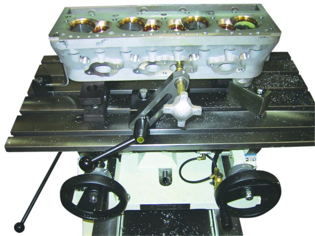
Rottler Dual Axis Leveling table. Achieves multiple angles while providing an extremely rigid mounting of the work piece. Critical to achieving super fine finishes.
The Fit Is In The Finish
By Larry Carley
Clean, flat and smooth. These three words describe the surface in an engine, not just the head and block. But how clean, how flat and how smooth do the surfaces really have to be to get a good, long lasting seal? It depends on the application.
Clean means no dirt, oil, grease or residual gasket material on either mating surface. Both surfaces must be spotlessly clean and dry to assure a good cold seal.
One thing to watch out for here is the use of cleaning solvents or gasket remover chemicals that leave residue on the surface. The residue may interact with the coating on or materials in a head gasket leading to premature gasket failure. So be sure to wash any chemical residue off the surface after the parts have been cleaned.
Also, some rebuilders use an abrasive pad in an air drill or buffer to buff off residual gasket material on head, block and manifold surfaces. It’s a quick and easy way to remove old gaskets, but it’s also risky because there’s a risk of removing metal and leaving a depression that will be hard to seal. For this reason, some experts say this approach should not be used to remove gaskets. Instead, hand scraping (carefully) or thermal or chemical cleaning should be employed.
Flatness
Flatness can be checked by placing a straight edge on the face of the cylinder head or block (be sure to check both!) and then using a feeler gauge between the straight edge and casting to check flatness.
On most pushrod engines with cast iron heads, up to .003" (0.076mm) out-of-flat lengthwise in V6 heads, .004" (0.102mm) in four cylinder or V8 heads, and .006" (0.152mm) in straight six cylinder heads is acceptable. The maximum allowable limit for out-of-flat sideways in any head is .002" (0.05mm) — with no sudden irregularities that exceed .001" in any direction.
Aluminum heads, on the other hand, should have no more than .002" (0.05mm) out-of-flat in any direction. If the clearance between the straight edge and surface exceeds the maximum limits, the head or block should be resurfaced.
Aluminum OHC heads should be checked for flatness in two places: across the face of the head with a straight edge, and down the OHC cam bores with a straightedge or bar. In most instances, both will be off if the head is warped. If the cam bores are still straight and only the face of the head is out-of-flat, resurfacing should be all that’s needed to make the head right. On the other hand, if the cam bores are out of alignment, the head will have to be straightened and/or align bored.
Aluminum heads can usually be straightened by bending. Some shops use a hydraulic ram to cold press the cylinder head, but there’s a risk of cracking or breaking the head with this technique. So most shops that straighten heads do so by counter shimming and bolting the head to a heavy, steel plate, then placing the head in an oven. Heat relaxes the head and reduces the risk of further cracking as it returns to shape. This can greatly reduce (or even eliminate) the amount of resurfacing that’s needed to make the head flat again.
Another technique for straightening aluminum heads involves spot heating various areas of the head with a torch. The thermal distortion that’s created can counter the warpage and essentially bend the head back into shape (see Automotive Rebuilder, December 1996, page 36, Straight Cylinder Heads In About Five Minutes?). This technique requires a fair amount of skill, but eliminates the need for fixturing or an oven.
Straightening aluminum heads prior to resurfacing greatly reduces the amount of metal that has to be removed to restore flatness. This minimizes changes in head height and often allows many heads to be repaired that would otherwise have to be replaced. The installed height of most OHC aluminum heads is fairly critical. Excessive milling lowers the height of the head which retards cam timing, reduces the volume of the combustion chambers and increases compression. Too much compression can cause detonation problems, which in turn can contribute to overheating and repeat head gasket failure.
When OHC aluminum heads are resurfaced, therefore, the amount of metal that can be safely removed is usually quite limited. Some heads have "indicator pads" on the casting that show how much material can be safely removed before the minimum height specification is exceeded. If the head can’t be straightened without exceeding the limit set by the pads, the head may have to be replaced — unless there is a head gasket shim available for the engine. The extra thickness of the shim can compensate for the metal removed to save many heads that would otherwise have to be replaced.
Surface finish
The issue of smoothness is one that is worrisome to rebuilders today. For many years, most aftermarket gasket manufacturers have recommended a head gasket surface finish of 55 to 110 micro-inches RA (roughness average), or 60 to 125 RMS (root mean square). The preferred range has traditionally been 80 to 100 RA. A surface finish on both the block and head that falls within the recommended range should provide good cold sealing and long term durability (assuming everything is assembled correctly and the head bolts are torqued in the proper sequence and to the specified torque).
Recently, though, some gasket manufacturers have changed their recommendations. Engines and castings have become lighter and less rigid. Many cylinder heads are now aluminum rather than cast iron. There have also been changes in head gasket materials and designs. So the recommendations for some engines now require a much smoother surface finish.
Some aftermarket gasket manufacturers now recommend a surface finish of 30 to 110 RA for cast iron head and block combinations, with a preferred range of 60 to 100 RA for best results.
For aluminum heads, the numbers are even lower. The typical recommendation today for an aluminum head on an OHC bi-metal engine is a surface finish of 30 to 60 RA, with the preferred range usually being from 50 to 60 RA.
Smoothness has become a major issue with bi-metal engines because the difference in thermal expansion rates between an aluminum head and cast iron block create a tremendous amount of sideways shearing force and scrubbing action on the head gasket. If the surface finish is too rough (more than about 60 RA), the metal will bite into the gasket and pull it sideways as the head expands and contracts. The cumulative effect over time can cause a delaminating effect in the gasket, literally tearing it apart and causing it to leak and fail.
Even lower numbers are recommended for some engines. General Motors specifies a surface finish of 27 to 47 RA for its 2.3L Quad Four engine when the OEM replacement gasket is used. Some aftermarket gaskets can handle a rougher finish on these engines, but it depends on the design of the gasket.
Very smooth surface finishes in the 20 to 30 RA range (or even less) are now required for some Ford engines such as the 4.6L V8 and its V6 modular offshoots. These engines, like a growing number of late model Japanese engines, have multilayer steel (MLS) head gaskets.
These laminated steel gaskets are extremely durable because the multiple layers of metal (each of which is coated with a thin layer of rubber) prevent the gasket from losing torque over time. The design also reduces the amount of torque that’s required on the head bolts to seal the gasket, which in turn reduces cylinder bore distortion for better combustion sealing and reduced blow-by.
When replacing the OEM head gasket on these engines, the surface must be restored to the same smoothness as it had from the factory. Some aftermarket gasket manufacturers are concerned that engine rebuilders and machine shops can achieve the high quality surfaces required for MLS gaskets, so are developing or have developed graphite or composite replacement gaskets for some applications such as the Ford 4.6L V8. These aftermarket replacement gaskets, say the manufacturers, can handle a more "traditional" (rougher) surface finish — but they may not provide the same longevity as the original MLS gasket.
"You don’t really need a 100,000 mile replacement gasket for the aftermarket," said one gasket engineer. "But you do need a gasket that will seal with a typical aftermarket surface finish."
Can the surface finish ever be too smooth? Although very smooth surfaces are required for MLS head gaskets, and smoother is generally better (up to a point) for most gaskets because it improves cold sealability, there is a limit. Most gasket manufacturers say the surface should not be smoother than about 30 RA for most non-asbestos or graphite head gaskets because of these gaskets’ lateral support from the head and block.
When the head is bolted to the block, the metal on both sides bites into the gasket to help hold it in place. You don’t want too much bite when the head is aluminum and the block is cast iron because of the sideways shearing forces that result from the expansion and contraction of the aluminum head. Yet, a certain amount of support is necessary to keep the combustion gases in the cylinders from distorting the gasket and blowing past it.
This is especially critical in the areas with narrow lands and between the head bolts where there is nothing to keep the gasket in place but the gasket itself. In high output or heavy-duty applications where combustion pressures exert even greater force against the head gasket, a surface finish that’s below the minimum smoothness spec might lead to premature gasket failure.
Surface condition
Another condition that can affect sealing is scratches. Every scratch is a potential leak path along which fluids and pressure can migrate. If a scratch is deep enough, coolant may find its way into the crankcase or cylinders before the engine is fired up. Or, combustion gases may force their way past the gasket into the cooling jacket or an adjacent cylinder, eventually causing the gasket to burn out and fail. If scratches, pitting or erosion are present on the head and/or block, resurfacing is required to remove the flaws.
Measuring surface finish
The only way to know if the finish you’re producing on a head or block is within specifications is to measure it. The least expensive way to do this is with a simple comparator gauge. Available from some aftermarket gasket suppliers as well as various tool suppliers, a comparator gauge has sample patches etched on a metal plate that indicate the different surface finish ranges. By placing the comparator gauge next to a resurfaced head, and visually comparing and feeling the sample patches on the gauge to the head, you can get an approximation of whether or not you’re in the correct range. It’s not exact science, but it can help you determine if you’re reasonably close to the desired finish.
The best way to determine surface finish is to measure it with an electronic surface profilometer. A profilometer measures surface finish by dragging a diamond-tipped stylus across the metal. This reveals the roughness of the surface as well as other important parameters that can tell you even more about what the surface is really like.
RA, or the roughness average, is an arithmetical average of the absolute values within the area sampled by the stylus. It gives you an approximation of surface roughness, plus other information that gives a more accurate picture of the surface’s true condition (things like the maximum peak-to-valley height (called "RY"), and the arithmetic mean of peak-to-valley heights ("RZ").
The ideal sealing surface is one that has neither large peaks or deep valleys, and provides a lot of flat bearing surface to support and seal the gasket.
Resurfacing techniques
The gasket manufacturers don’t care what type of resurfacing techniques or equipment rebuilders use to resurface heads and blocks as long as the RA numbers end up in the recommended range. It is possible to achieve an acceptable surface finish for a soft-faced head gasket on most cast iron and even aluminum heads by milling, grinding or belt sanding.
However, for engines with MLS head gaskets, and even some of the aluminum heads that require a smoother than usual finish (like the 2.3L Quad Four), milling or grinding may be the only sure way to achieve the lower RA numbers required. Be warned, though, that the spindle and bearings in older milling and grinding equipment may not be designed to meet the resurfacing requirements of today’s engines. Consequently, some machines that are more than about five years old may not be capable of producing these really smooth finishes. Check with your equipment supplier if you have any doubts.
Grinding
In the past, many heads were resurfaced by wet grinding. It is still used by many shops because grinding can produce a very smooth finish. Silicon carbide grinding wheels and segments are generally recommended for both cast iron and aluminum. Grinding aluminum, however, can be tricky because the stone tends to load up with metal, causing it to overheat and score the surface. So the aluminum needs to be pre-coated with lubricant and resurfaced with plenty of coolant to prevent clogging.
A faster transverse speed may also be needed with aluminum, and the depth of cut limited to no more than .0005" to .001". The machinist should also dress the grinding wheel often to keep the grain open — but not on the final pass so the stone will leave a smoother finish.
Milling
Many shops today have switched to dry milling because it eliminates the mess and maintenance that go with wet grinding. Milling allows very precise control over stock removal, and it is faster than grinding because more metal can be removed in a single pass, eliminating the need for multiple cuts.
The key to achieving the smoother finishes required by many of today’s aluminum heads is using the right combination of table feed and rpm when milling the head. This requires a variable speed table and/or multi-speed or variable speed milling head. Increasing the rpm of the cutting head and/or slowing down the feed rate produces a smoother finish. One equipment manufacturer, for example, recommends a feed rate of two inches per minute at 1,000 rpm on a milling machine with a two-bladed cutter to achieve a surface finish of 12 RA.
Carbide or PCD (polycrystaline diamond) tooling is usually recommended for milling aluminum, while carbide or CBN (cubic boron nitride) is recommended for milling cast iron.
Belt sanding (Not recommended for modern gasket sealing)
Belt sanding is a quick way to resurface a head because the head doesn’t have to be mounted in a fixture. But it isn’t as precise as milling or grinding. Results often depend on the expertise, experience and skill of the individual operator. The amount of downward pressure exerted by the operator on the head, the weight of the head itself, how the head is positioned on the sander and the condition of the belt can all affect the results. Consequently, some say belt sanding is better suited for clean-up work or resurfacing hard-to-fixture parts like manifolds and timing covers rather than resurfacing heads on late model engines.
For resurfacing aluminum, silicon carbide belts are generally recommended. Silicon carbide can also be used for cast iron, as can aluminum oxide or other ceramic based abrasives. Either #40 or #80 grit belts can be used with aluminum, but #80 grit is the preferred choice and should be used with no downward pressure on the head.
It’s also important to replace the belt regularly because a dull belt can overheat the head causing warpage and an uneven surface finish.
In sum, today’s lighter weight, bi-metallic engine designs usually demand stricter control of surface finish requirements in order to seal properly. New replacement gasket designs, along with the right equipment, is necessary to ensure your customer is happy with the performance of their rebuilt engine.
Engine Gaskets 101
